World leader in customized focused ion and electron beam technology
Scientific Overviews
What is UHV?
UHV stands for Ultra High Vacuum. As the vacuum is the absence of material, what is in fact measured is the pressure of residual gas in the chamber. Vacuum represents particle density lower than the atmospheric pressure. Three different units are commonly used: Pa, Torr and mbar (1 Pa is 7.5.10-3 Torr and 1.10-2 mbar). The vacuum “quality” is classified in 3 ranges: Rough, high and Ultra high Vacuum (see fig. 1a).
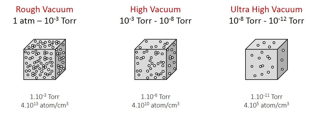
Figure 1a. Vacuum comparison schematic
An ion or electron beam which encounters particles (residual gas inside the chamber) will be deflected, divided, or even reacted with them. The Mean Free Path (MFP) is the average distance a gas molecule travels before it collides with another gas molecule and in the above examples, at a pressure of 1.10-3 Torr the MFP is 5cm and 50 km at 1.10-9 Torr.
Depending of the requested vacuum, rough pump, turbo molecular pump or ionic pump can be used independently or in combination.
- Rough pump down to around 10-3 Torr
- Rough pump + Turbo molecular pump down to around 10-8 Torr
- Rough pump + Turbo molecular pump + ionic pump down to 10-11 Torr (note that it is also necessary to bake out the chamber to obtain UHV).
In terms of application, the main issue is not the pressure value itself but the contamination of the sample. The more residual gas molecules are present in the chamber the more the sample surface will absorb some atmospheric particles, decreasing the analysis quality over the time. That’s why, the study and the sample analysis will be more accurate and precise if the vacuum is as low as possible.
Ultra-High Vacuum (UHV) is a very interesting vacuum range for surface analysis. Indeed, in the HV range a monolayer deposits every 4 seconds, and in the UHV range a monolayer deposits every 4 days (see fig. 1b).
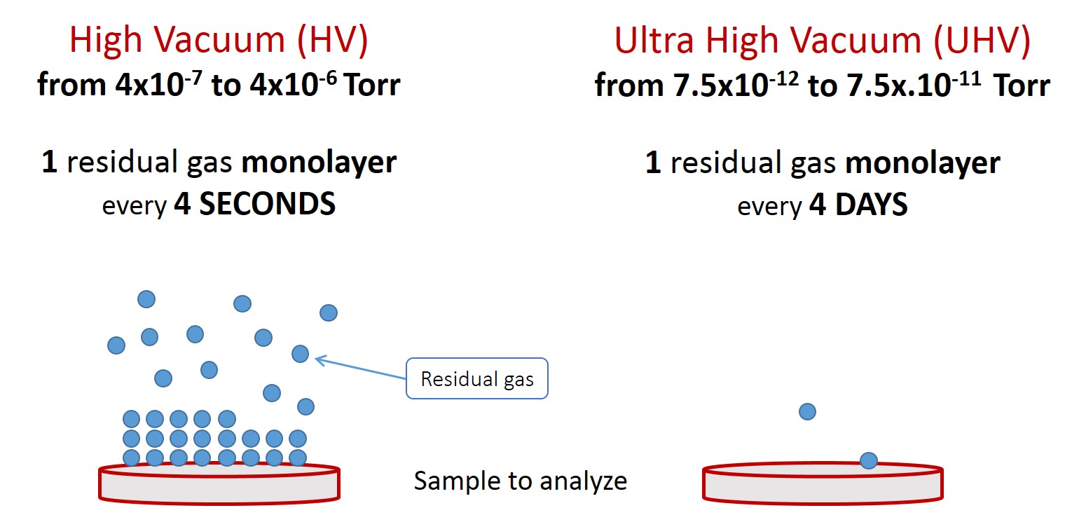
Figure 1b. HV and UHV comparison schematic
How to achieve UHV?
These vacuum levels demand the use of special materials and pumping procedures. Seals and gaskets used in a UHV system must prevent even trace leakage. Therefore, nearly all such seals are all metals, with knife-edges on both sides cutting into a soft gasket, typically copper. These all-metal seals can maintain integrity to UHV ranges.
The materials used in UHV condition need to stand heating at more than 120°C for many hours/ days but also shouldn’t present high vapor pressure. So, it is not possible to use plastics, PTFE, PEEK neither glue (screws are used instead), lead (soldering). This a reason why UHV chamber are more expensive than conventional vacuum one’s.
Moreover, the process of baking removes gas atoms from the chamber wall surfaces. These gas atoms slowly desorb from the chamber wall surfaces, and if the chamber was not baked, it would literally take months before the chamber achieved UHV conditions. The vacuum chamber is enclosed in heat resistant material, and baked to a temperature of about 180°C (355°F). After some hours of baking, the ovens are removed, and the chamber allowed to cool down. Once at room temperature, the chamber should have a pressure in the UHV region.
Whereas the dominant species in HV is usually water, UHV is almost 100% dry and hydrogen is the most prevalent residual gas. Hydrogen is light and mobile and very difficult to pump, requiring specialized UHV pumps and reducing the gas load from the chamber walls is paramount.
Why do we need UHV environment?
Many surface analysis techniques would not be possible without a clean UHV environment. Analysis techniques such as AES (Auger electron spectroscopy) or SIMS (Secondary Ion Mass Spectrometry) (fig. 2), and thin film techniques such as the epitaxial growth of nanowires (fig. 3) require high purity over a sustained analysis time and thus are prime candidates for UHV.
UHV is also used for particle accelerators, gravitational wave detectors, atomic physics and microscopy (e.g. atomic force and scanning tunneling). In addition, UHV is required for most surface science analysis for two principal reasons:
- To enable atomically clean surfaces to be prepared for study, and to maintain those surfaces in a contamination-free state for the duration of the experiment.
- To permit the use of low energy electron and ion-based experimental techniques without undue interference from gas phase scattering.
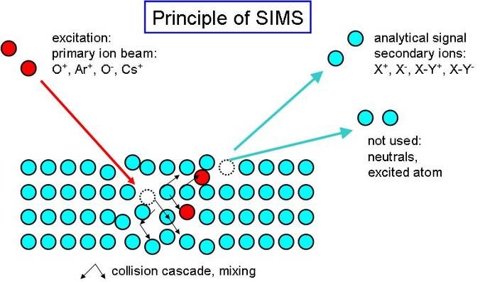
Figure 2. Schematic SIMS principle
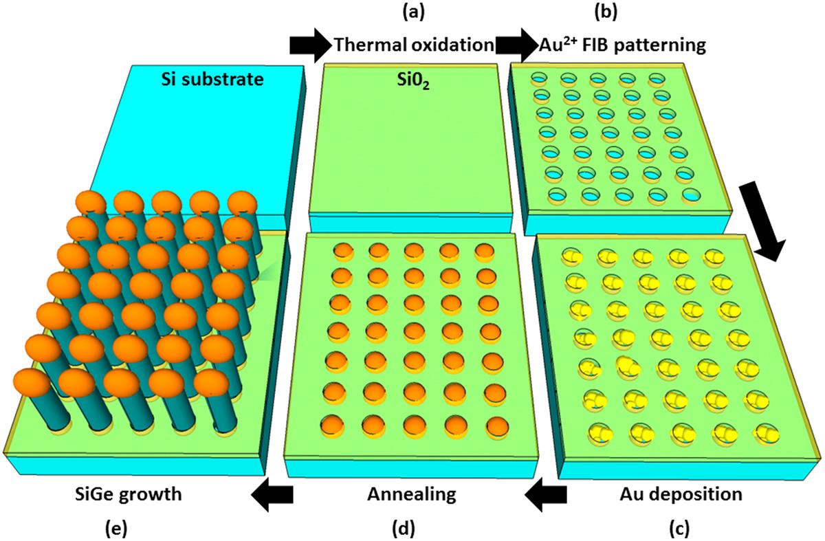
Figure 3. Schematic representation of SiGe nanowires (NW) fabrication process
(a) Formation of SiO2 by Rapid Thermal Oxidation (RTO)Opening of SiO2-free windows by FIB milling
(b) Au deposition by oxydoreduction of gold salts
(c) Phase transition of Au in AuSi clusters by annealing
(d) MBE growth of SiGe Nanowires
From A. Benkouider et al., Nanotechnology 25 (2014) 335303